
15. Mobile Application
The oneView application supports both Android and IOS phones and tablets. You can find the Level Up application in there respective app stores. The application is free to download. The same application is used for both Level Up Lite and Level Up Pro editions of the mobile.
15.1. Installation
15.1.1. oneView for Android
To download oneView for Android, scan the QR code or click on the link below :

Download oneView for Android
https://play.google.com/store/apps/details?id=ca.sigmaiq.oneview
Permissions Required:
Access locations extra commands
Access wifi state
Bluetooth
Bluetooth admin
Internet
Access course location
Access fine location
15.1.2. oneView for IOS
To download the oneView for Apple IOS devices click on the following link :

Download oneView for IOS
https://apps.apple.com/app/oneview/id6463253309
To download the oneView for IOS click on the following link :
Permissions Required:
NSLocationWhenInUseUsage
NSBluetoothAlwaysUsage
NSBluetoothPeripherialUsage
15.2. Getting Started
15.2.1. Location Usage Statement
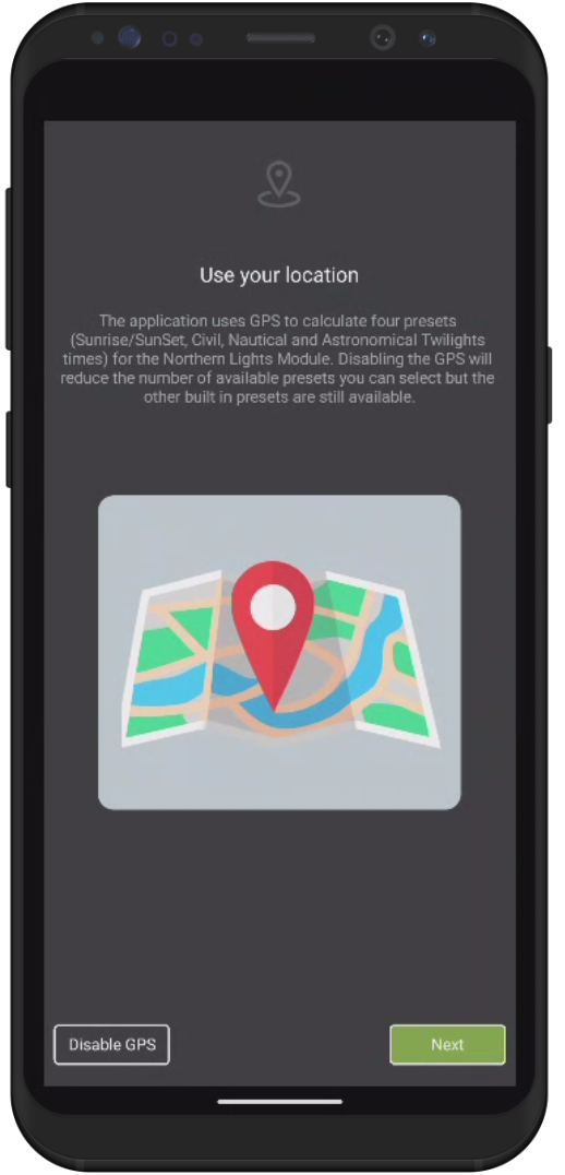
The oneView application when first launched will display the “use your location” screen on Android devices. This screen will only appear once and allows you to opt in/out of the following features:
to use GPS for geo pinning your RV every time it is parked.
use the Time Presets with the Northern Lights module. GPS is used along with your mobile devices time and date to accurately calculate sunset and sunrise time.
If you choose “Disable GPS” then oneView application will disable all GPS usage inside the application.
Note
The location usage screen only appears on Android devices.
15.2.2. Adding a Trailer
Pairing your Level Up and Northern Lights module to oneView
Once oneView is installed on your mobile device and you have allowed the requested permissions, you should be greeted with an empty My Trailers screen. The oneView application will start searching for your oneView module. In order for the mobile application to find the oneView module, the module needs to be on (PWR indicator lit).
If it is does not appear there are a few things to check:
ensure that the battery is installed
Confirm you have connected up external power (12 VDC or USB)
Ensure that you don’t have another mobile device currently connected to the oneView module. If so, simply exit out of the application on that device. The BLE LED indicator will go off once it has detected the disconnection. The oneView module will begin to broadcast is presence.
To prevent others from inadvertently connecting to your oneView module, oneView utilizes a four digit pin to authenticate your device or devices to the module. The factory default pin is 0000. The pin is stored in the oneView module and in the oneView mobile application. Each trailer that you have a oneView module installed on can have its own unique pin code. The security pin is automatically sent by the mobile device to the oneView when attempting to connect. You do not have to enter the code every time you connect. The PIN is encrypted when sent from the mobile device to the oneView module.
Things to do:
Change the PIN code when setting up the system.
Store the PIN in a safe place (Password Locker)
Never use your bank PIN or any other secure code for your oneView PIN
15.2.3. Updating Your Security PIN
Tap on the menu icon on the top left of the screen. Choose Settings. Tap on any of the four of the security pin digits to enter a new PIN. Once the new pin is enter press ENT. You will be returned to the settings screen. The new pin is automatically saved on your mobile device.
15.2.4. Connecting to the Trailer

Connecting to Trailer
Trailer Profiles
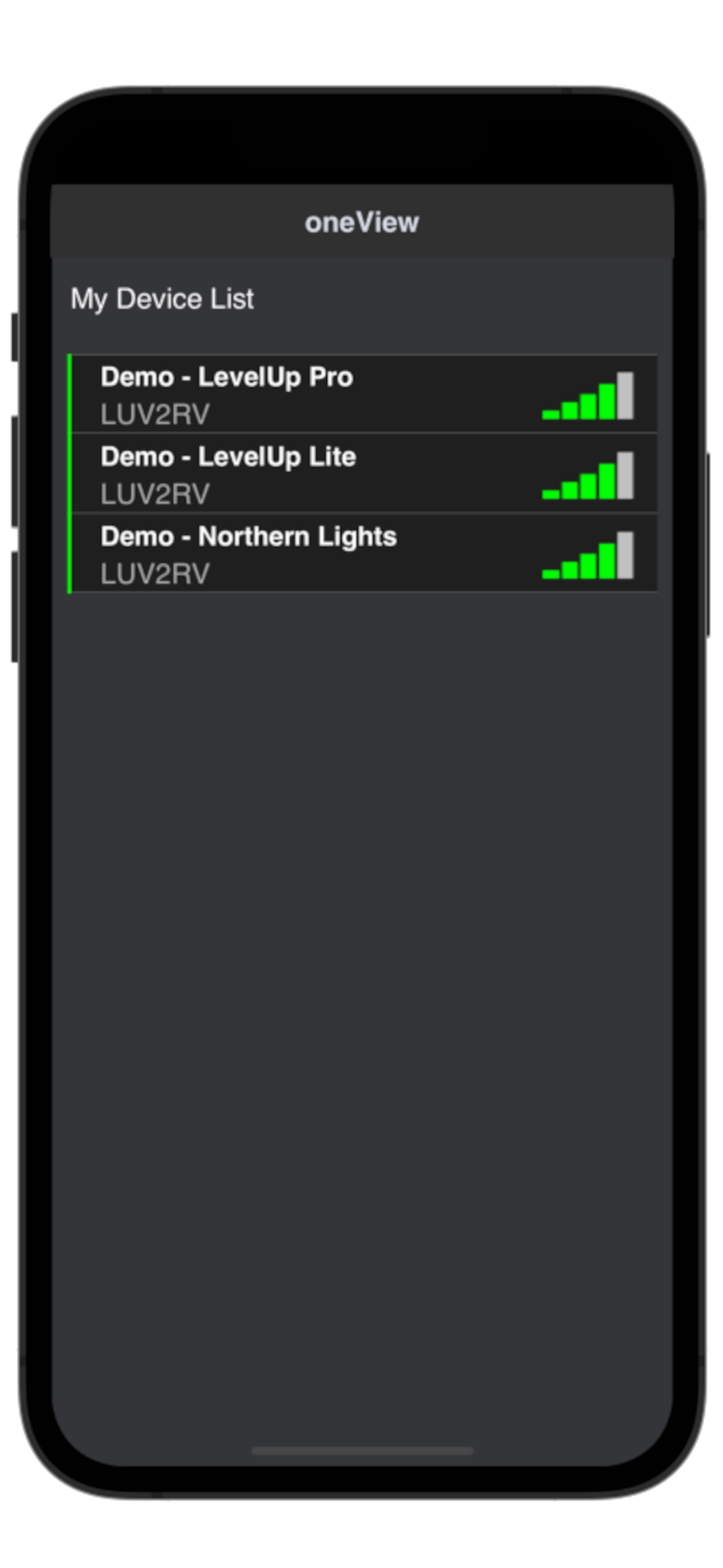
Once the oneView mobile application starts, you will be presented with a list of trailer profiles that oneView knows about. The oneView application allows you to store multiple trailer profiles. oneView will show which trailers are in range of your mobile device (assuming the Level Up and Northern Lights module are not in sleep mode) with a black bar (not seen) or a green bar (seen) to the left of the trailer name.
The mobile application will also show the signal strength (RSSI) to the right of the trailer profile.
By tapping on the desire trailer profile, oneView will attempt to connect to the oneView module. The application will display a spining please wait icon. It may take a couple of seconds for the mobile application to connect to the oneView module. Along with establising a connection the oneView module is checking the credentials sent by the application.
Icon |
Description |
|---|---|

|
Previously saved trailer, that is currently not in range of your mobile device. You can not connect to this device.
Move closer |

|
New or previously saved trailers. You can connect to these devices by tapping on the trailer name. |
15.2.5. Signal Strength
Icon |
Description |
Signal Strength |
|---|---|---|

|
Your mobile is out of range of the oneView module or oneView module is sleeping |
Less than -90 dBm |

|
Your mobile device is in range of the oneView module, but you may experience intermittent |
-85.1 dBm to -90 dBm |

|
Your mobile device is in range of the oneView module, but you may experience loss of |
-80.1 dBm to -85 dBm |

|
You mobile device is in range of the oneView module and you will have no issues connecting |
-75.1 dBm to -80 dBm |

|
Your mobile device is in range of the oneView module and you can expect a solid connection |
-70.1 dbm to -75 dBm |

|
Your mobile device is in range of the oneView module and you can expect no connection issues. |
Greater than -70 dBm |
15.3. Dashboard
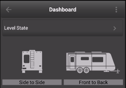
The Level State section in the dashboard provide a quick view of the trailer level state. The dashboard does not show how much the trailer is out of level, only that it is uncalibrated, level, or not level.
Uncalibrated Level State |
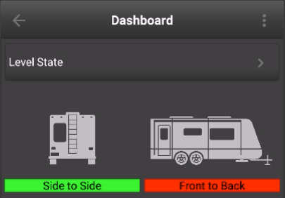
Calibrated Level State |
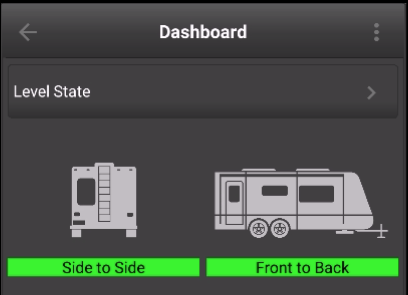
Calibrated Level State |
To get additional detail on the trailer level state tap on the right arrow in the Level State header.
15.3.1. Level State
Once you selected the trailer to connect, the application launches the dashboard. Level Up displays a snapshot of all the sensors, such as trailer level state, internal sensors (Pro Only) , external sensors (Pro Only), EMS Status (Pro Only) and Events. The top of the dashboard contains a back arrow that disconnects your from your current trailer profile takes you back to the list of trailers. The three vertical dots on the top right will popup the main menu. You can tap on the popup menu any time you need access to general settings, trailer settings, ems settings etc.
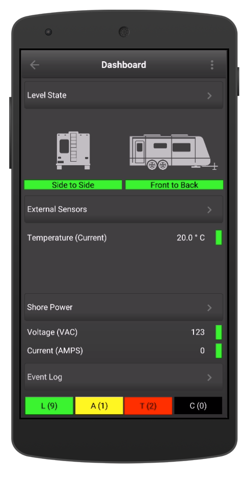
Dashboard |
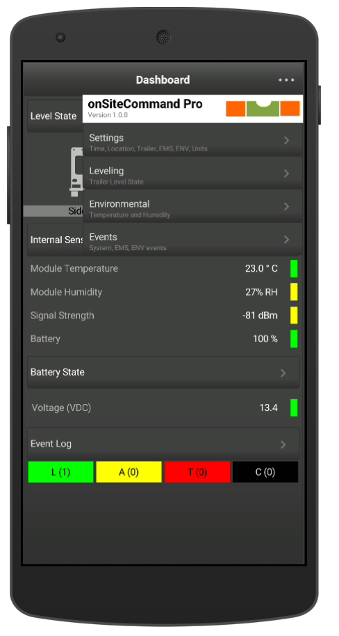
Popup Menu |
15.3.2. Internal Sensors
The Level Up Pro modules contain an internal temperature and humidity sensor, that can be used to monitor the environmental status of the compartment you installed the module in your RV. If you would like to monitor temperature and humidity inside the living area of your RV, we would recommend looking at purchasing some external sensors.
Sensor |
Range |
|---|---|
Temperature |
-40 to +125 C |
Humidity |
0 to 100 %RH |
Warning
The internal temperature and humidity sensor may not accurately reflect the actual temperature and/or humidity due to the module installation. For example if you install the Level Up Pro module in an enclosed space adjacent to the hot water heater or the furnance you will see results that are higher than ambient temperature and humidity.
15.3.3. Event Status
At the bottom of the dashboard is the event summary. Level Up classifies the events in to Log, Attention, Trouble and Critical. The dashboard includes the event counts for each of the event type.
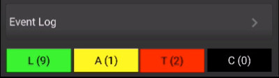
When clicking on the event type (green,yellow,red or black) button, Level Up will take you the event summary screen and automatically filter the events for the type you tapped on. For example if you tap on the Attention (yellow) you would taken to the events summary screen and be shown a single Attention Event. Choosing to tap on the arrow to the right of Event Log takes you to the event summary page will display all the events currently on the system.
15.3.4. EMS Summary
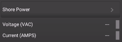
EMS - No Shore Power Detected |
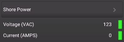
EMS - Shore Power Detected |
Voltage (AC)
Icon |
Description |
|---|---|

|
No Shore Power |

|
Voltage to Pedestal and the voltage is between 114 and 126 VAC |

|
Voltage is between 104 VAC and 114 VAC or voltage is between 126 VAC and 132 VAC |

|
Voltage to Pedestal but the voltage is lower than 104 VAC or greater than 132 VAC |
Note
In North America the standard is ± 5 % from the nominal 120 VAC. That puts the acceptable voltage range between 114 and 126 VAC. Progressive Industries considers anything from 104 VAC to 132 VAC acceptable. See Page 7 of the Progressive Industries manual for more information on voltage ranges).
Current (ACI)
Icon |
Load % |
EMS-HW30C (AMPS) |
EMS-HW50C (AMPS) |
|---|---|---|---|
|
|
0 |
— |
— |
|
|
0.1 - 50 |
Less than 15 AMPS |
Less than 25 AMPS |
|
|
50.1 - 75 |
Between 15.1 and 22 AMPS |
Between 25.1 and 36 AMPS |

|
75.1 - 90 |
Between 22.1 and 27 AMPS |
Between 36.1 and 45 AMPS |
|
|
90.1 - 100 |
Between 27.1 and 30 AMPS |
Between 45.1 and 50 AMPS |
Note
The color ranges for the load current are a function of the Level Up Pro application and not of the Progressive Industries EMS.
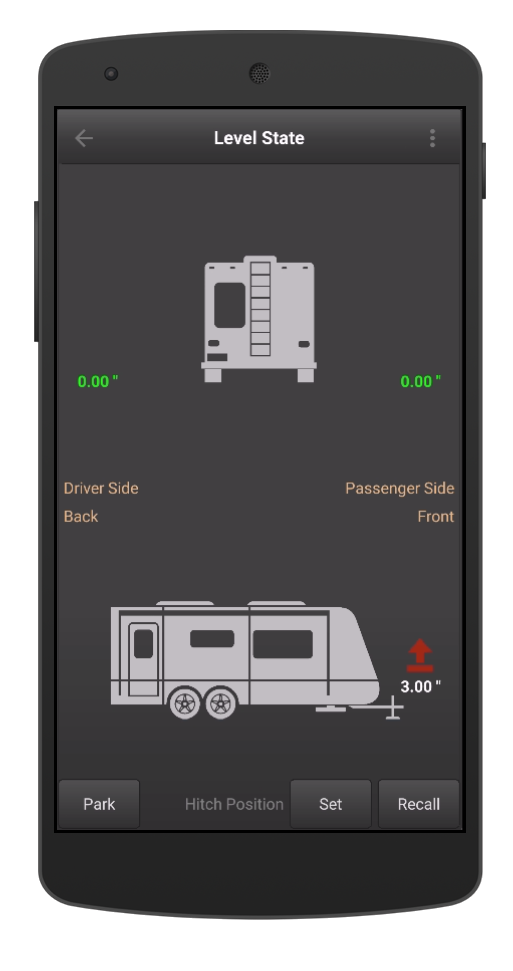
15.4. Levelling Screen
To access the levelling screen tap on Level State button on the dashboard. The screen shows a side to side view as well as a trailer profile view. In the side to side view the Level Up application is always referenced relative to the drivers side (left side) of the trailer. The front to back is always referenced off the back of the RV (i.e. the tongue is 1.5” inches higher than the back of the trailer).
The calibration banner will only appear on the level screen if the calibration process is underway. Once the calibration is complete the Level Up application will save the settings. The calibration banner will automatically disappear when complete.
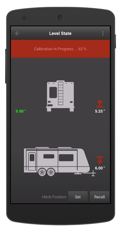
Level State - Calibration in Progress |
Level State - Normal Mode |
Icon |
Description |
|---|---|
|
The trailer is level within the measurement resolution setting. |

|
The trailer is high (front to back or side to side). |

|
The trailer is low (front to back or side to side) . |
15.4.1. Hitch Height Recall
The hitch height recall allows you to save the hitch height when unhooking your RV. The saved hitch height is useful when rehooking the RV
15.4.1.1. Set
Unhook the RV and with the ball or fifth wheel pin high enough to clear the hitch press the Set button on the Level Screen.
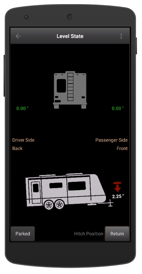
15.4.1.2. Recall
When hooking the trailer to the tow vehicle, return to the level state screen and press the Recall button The background will change to black. The indicator at the front of the RV will change to show the how hight the RV hitch will need to be raised. When the icon goes green you know the hitch is high enough to clear the the ball and/or the pin.
Important
Never assume the trailer tongue/pin will clear without double checking.
15.4.2. Trailer Tilt Charts
To view the roll and pitch of your trailer tap on either of the trailer icons in the Level State screen. The tilt graphs can be viewed together (by tapping all - not shown) or by tapping the Pitch or Roll button on the top right. The back arrow will take you back to the Level State screen.
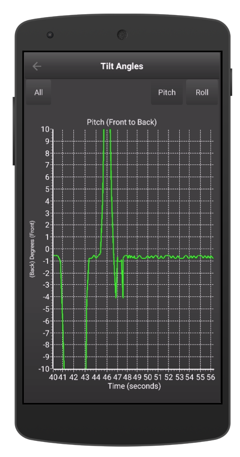
Tilt Angle - Pitch (Front to Back) |
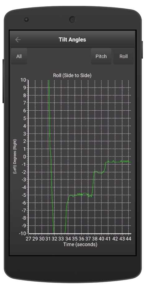
Tilt Angle - Roll (Side to Side) |
The pitch and roll are displayed in degrees. If your trailer is level the lines on the graphs should be around the 0 degree mark (center of the graph).
15.4.3. Motion
The motion section on the dashboard displays the latest movement of the trailer when the trailer is parked. In order for this section to appear in the dashboard your trailer must be marked at Parked (Level Screen), and you must have a oneView Pro module. The LED bar shows the last ten minutes of movement and the color is based on the severity of the movement. Each minute is represented by one bar. The bars are populated so the latest movement appears on the right.
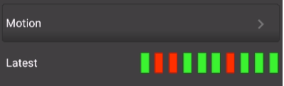
Motion Detected - Red Indicates Motion |
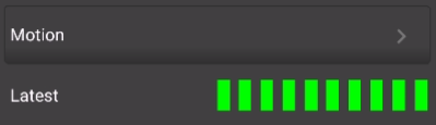
No Motion Detected - Green Indicates no Motion |
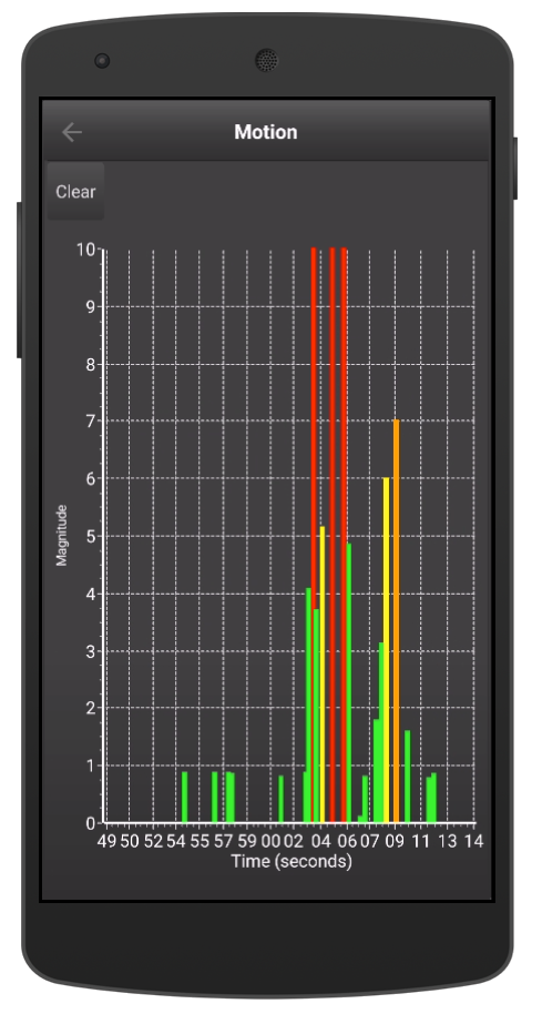
For more detail on the motion and the severity tap on the right arrow in the motion section header. Tapping on the motion (in the dashboard) label (or arrow) displays the magnitude over time graph.
15.4.3.1. Movement Severity
Type |
Description |
|---|---|
|
|
The magnitude is less than 5 |
|
|
The magnitude is between 5 and 7 |
|
|
The magnitude is between 7 and 10 |
|
|
The magnitude is above 10 |
15.5. Settings Screen
15.5.1. General Trailer Settings
The General Trailer Settings allows you to customize your trailer name, as well as include the trailers license plate. The Master Events Control allows Level Up Pro modules to enable/disable events globally should they decide.
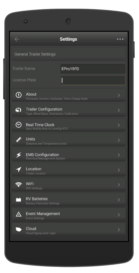
Trailer Name
The Level Up application allows you to assign a custom name to your RV. The default name is based on the Level Up module and the serial number (MAC address) of the device. For example if you are connected to the Pro module the name will be something like SIQ-LevelUp Pro-57b116 or if you are connected to the Lite version SIQ-LevelUp Lite-57b118.
License Plate
Use the trailer plate field to enter your RV license plate, or if you prefer enter the license plate of the tow vehicle. That way when you are registering at the campground or RV park you can use the Level Up application to view your license plate, and not run back into the parking lot to double check (ask me how I know). You don’t need to connect to actual module, the license plate will appear below the module name on the connect screen.
15.5.2. About
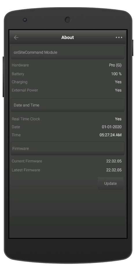
The about screen provides an overview of the Level Up module firmware and hardware. For more information on the hardware and firmware check out the Revisions section of the help for a list of all the changes, fixes and new feature.
Note
Upgrading the Level Up module requires the an active WiFi connection. The Update button will only be enabled if a newer version of the firmware was detected.
15.5.3. Trailer Configuration
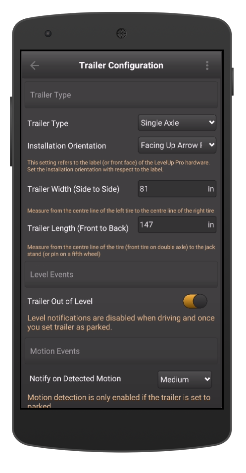
Trailer Type
Drop down allows you to customize the type of trailer you own. Options are Single Axle, Double Axle, Fifth Wheel, Class A, Class B, and Class C. The trailer type has no impact on the actual performance or calculation it simply selects the RV icon in the Level Screen and the dashboard.
Installation Orientation
Specifies how the Level Up module is installed in the RV. This parameter is critical to the calibration process. If you relocate the module, or change this setting you will need to physically level the trailer and rerun the calibration process. To recalibrate your trailer check out the Manual Calibration Process.
Trailer Width (Side to Side)
Enter the wheel spacing from the center of the passenger tire to the drivers side tire. The units will be based on the units set in Settings | Units. The current unit settings are embedded in the field.
Trailer Length (Front to Back)
Enter the distance from the front most axle on a towable or fifth wheel to the tongue jack and/or pin.The units will be based on the units set in Settings | Units. The current unit settings are embedded in the field. For more details on making the measurements click here.
15.5.4. Units
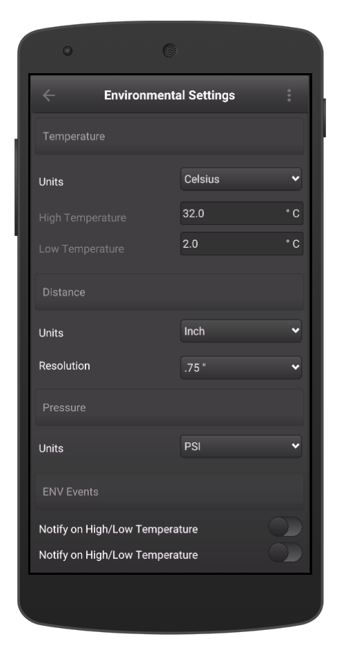
15.5.4.1. Temperature
oneView can display temperature in Celsius and Fahrenheit. Select your preferred temperature units from the drop down box. Note: Native units for temperature measurements in Level Up are degrees Celsius. If you choose Fahrenheit in the mobile application the degrees Celsius is converted using the formula below:
15.5.4.2. Distance Units
oneView allows you to set your preferred Distance units. oneView supports:
inches
mm
cm
Note
The oneView application Internally converts all measurements regardless of the distance unit type selected is always converted to mm. This can in some rare instances lead to some small rounding errors.
15.5.4.3. Resolution
The resolution setting is used to avoid the leveling screen from oscillating from red (not level) to green (level) whenever the Level Up module detects a small change (i.e. someone waking through the trailer). The resolution setting is the minimum amount of change the trailer needs to move either side to side or front to back before the level screen updates.
When the distance units is set to inches the resolution options are :
0.25”
0.50”
0.75” (recommended)
1.00”
When the distance units are set to mm the resolution options are :
05.0 mm
10.0 mm
20.0 mm (recommended)
25.0 mm
When the distance units are set to cm the resolution options are :
0.5 cm
1.0 cm
2.0 cm (recommended)
2.5 cm
Note
As Level Up stores all distance measurements in mm, the resolution may not be exact for all unit types. For example if you set the units to inches and choose 1.00” as the resolution, the oneView actually converts the 1.00” and stores it as 25 mm not 25.4 mm. The table below shows the measurement resolution “error”:
15.5.4.4. Max Unit Errors Between Metric and Imperial
Resolution Settings (inches) |
Converted from inches to mm |
Actual Resolution Used (mm) |
Error (mm) |
|---|---|---|---|
0.25 |
6.36 |
5 |
+1.35 |
0.50 |
12.7 |
10 |
+2.70 |
0.75 |
19.05 |
20 |
-0.95 |
1.00 |
25.4 |
25 |
+0.40 |
It is important to note that the error is not compounded as a function of length or width of the trailer. The resolution setting is only used as hysteresis to prevent the Level State screen from oscillating between level (green) and not level (red) when for example someone is walking through the trailer.
15.5.5. Real Time Clock
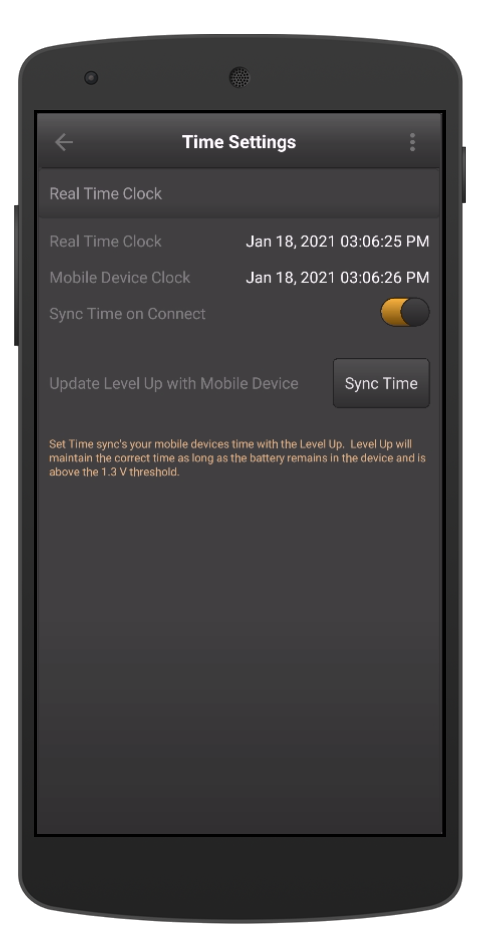
The Level Up Pro has a real time clock installed that is battery backed up and can maintain the current date and time even if there is insufficient battery life left to fully power up the Level Up module.
To set the real time clock simply go to Settings | Real Time Clock. The oneView application will display the current date and time of the Level Up module as well as the current date and time of your mobile device.
To set the time on the Level Up module simply press the Sync Time button. Sync’ing your mobile devices date and time to the Level Up module will only take a few seconds. Once the time is set you will notice that the Real Time Clock field and the Mobile Device Clock will match.
If you wish to automatically set the real time clock slide the Sync Time on Connect switch. This will automatically update the Level Up module with the correct date and time every time the Level Up application is launched.
15.6. EMS Screen
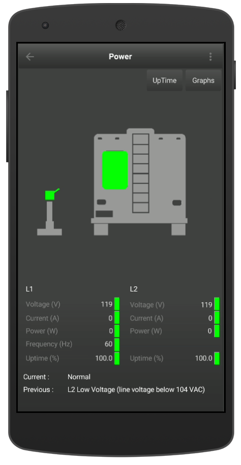
EMS Status Screen -50 AMP
The Level Up Pro module displays the current state of the Progressive Industries EMS module. The screen displays the status of the pedestal as well as the power to the RV. The screen also displays:
Parameter |
Range |
Unit |
|---|---|---|
L1 Voltage |
103 to 132 |
VAC |
L2 Voltage |
103 to 132 |
VAC |
Current (30 AMP) |
0 to 30 |
AMPS |
Current (50 AMP) 1 |
0 to 100 |
AMPS |
Power (30 AMP) |
0 to 3600 |
Watts |
Power (50 AMP) |
0 to 12,000 |
Watts |
Uptime |
0 to 100 |
% |
Frequency |
51 to 69 |
Hz |
Footnotes
- 1
A 50 AMP circuit supports a combined total of 100 Amps - L1=50 AMPS and L2=50 AMPS
Pedestal Icon Colors
Description |
State |
|---|---|
Power Detected and in Normal Range |
|
No Power Detected but outside of Normal Range |
|
RV Icon Colors
Description |
State |
|---|---|
No Power in RV |
|
Power In RV |
|
The current and previous EMS states are shown at the bottom of the screen. For a list of the error codes and descriptions click here.
15.6.1. 30 AMP Service
If your trailer is equipped with a 30 Amp service your power connector will have a three prong connector (hot, neutral and ground). In a 30 Amp service the hot is also referred to L1.
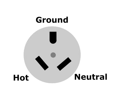
30 AMP Plug
15.6.2. 50 Amp Service
If your trailer is equipped with a 50 Amp service your power connector will have four prongs (Hot L1, Hot L2, ground and neutral). The EMS status screen will show power, current and uptime for both L1 and L2 circuits simultaneously.
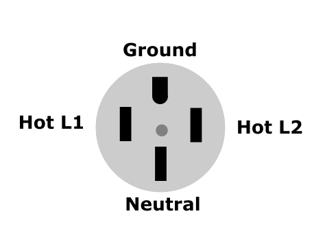
50 AMP Plug
15.6.3. EMS Graphs
The EMS graphs allows you to see the voltage, current and frequency from your EMS over time. SIQ only stores the changes so if the voltage, current and frequency are the same as the previous measurements the results are discarded. This saves memory and storage space with out the loss of any data. You can view the L1 and/or L2 circuit and then choose the parameter you wish to monitor (volts, amps, freq).
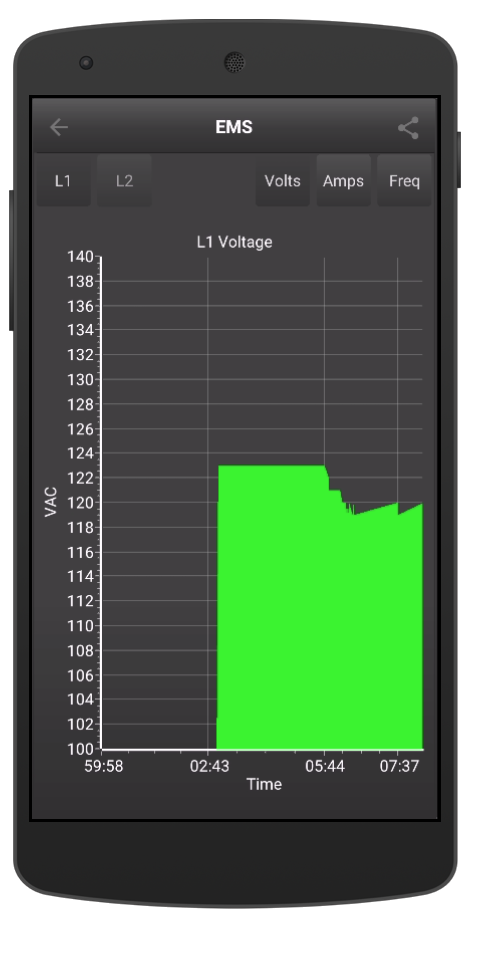
EMS - Voltage vs Time |

EMS - Current vs Time |
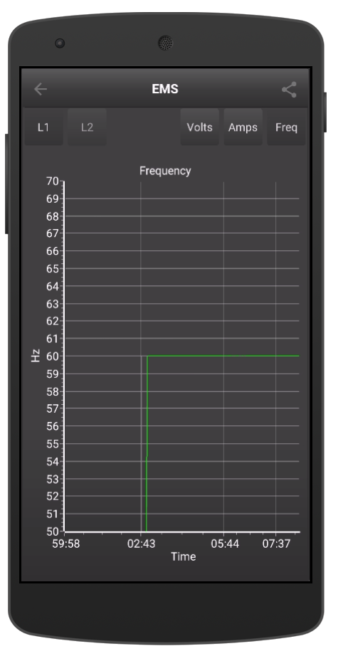
EMS - Frequency vs Time |
Note
There is only one frequency graph regardless if you are displaying L1 and/or L2 as the frequency is common to L1 and L2.
15.6.4. EMS Uptime Graphs
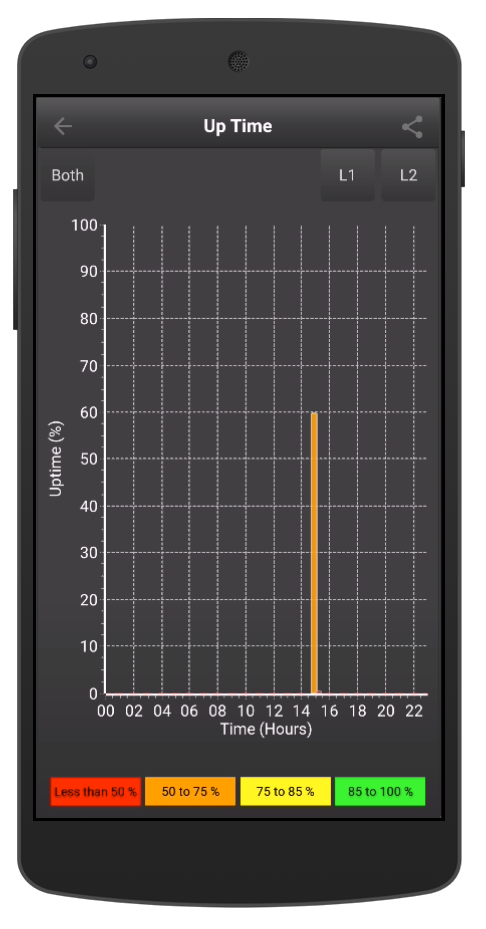
EMS - Uptime
The EMS Up Time graph displays the total time the EMS detect power from the pedestal. The uptime is only considered if the EMS status is Normal (E 0), if the voltage, frequency is out of the valid range as per the Progressive Industries Manual (Page 7) or there is a wiring fault oneView will consider that as down time. oneView stores the last 24 hours of Uptime and then removes the oldest hour and replaces it with current data.
15.6.5. EMS Error Codes
The EMS Error codes are defined by the Progressive Industries EMS module. The table below is taken directly from the Progressive Industries manual page 7 - Error Code Chart.
Error Code |
Description |
|---|---|
E0 |
Normal Operating Condition |
E1 |
Reverse Polarity (hot and neutral wires are reversed). |
E2 |
Open Ground (no ground wire connection) |
E3 |
Line 1 (L1) High Voltage (line voltage above 132 V) |
E4 |
Line 1 (L1) Low Voltage (line voltage below 104 V) |
E5 2 |
Line 2 (L2) High Voltage (line voltage above 132 V) |
E6 2 |
Line 2 (L2) Low Voltage (line voltage below 104 V) |
E7 |
Line Frequency High (line frequency above 69 Hz) |
E8 |
Line Frequency Low (line frequency below 51 Hz) |
E9 3 |
Data Link Down |
E10 |
Replace Surge Protection Module (call Progressive Industries Tech Support) |
oneView Pro has added two additional status codes based on the state of the EMS.
Error Code |
Description |
|---|---|
E89 |
Power to the pedestal, but no power to the RV. |
E99 |
No Power to the pedestal |
Footnotes
- 2(1,2)
Error Code 5 and 6 only apply to EMS-HW50C models
- 3
If the Progressive Industries display module is displaying E9 - Data Link Down. We would recommend removing shore power, and reconnecting the display directly into the Data port of the EMS. If the problem persists we would recommend changing out the data cable with the one that was supplied with the oneView Pro to see if this corrects the issue. If replacing cable fixes the issue, we would recommend you replace the defective cable. If the E9 error persists contact Progressive Industries support.
15.7. Events
oneView has an integrated event system, that logs events that occur due to a detected faults (Progressive Industries EMS errors), or triggered by some system event (such as motion, or mobile device connections), etc. Events that are generated are set with a severity classification and assigned to an event category.
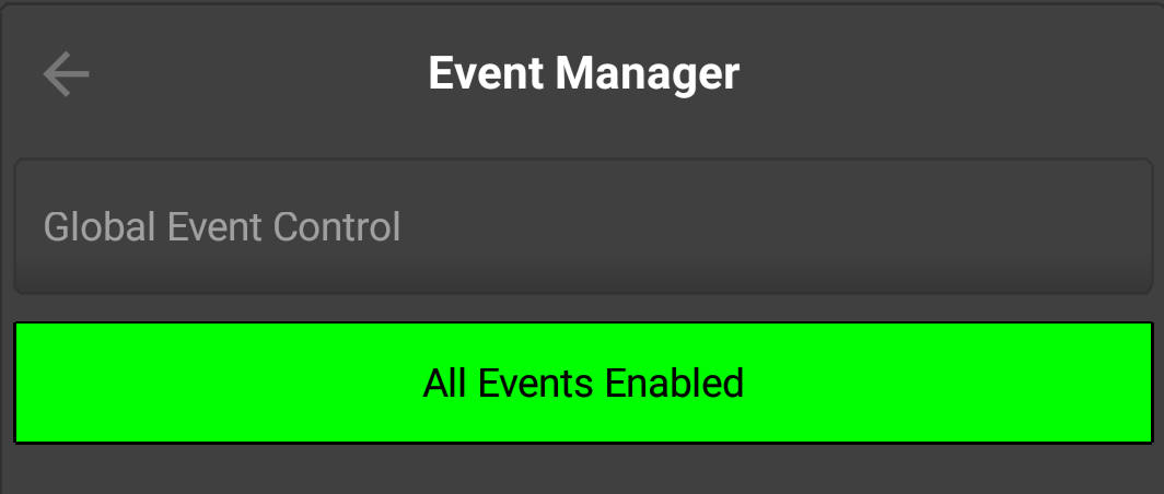
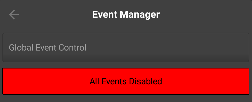
15.7.1. Global Event Control
Events in Level Up Pro (only) can be enabled or disabled globally from the Settings screen by tapping on the Master Events Control. This allows you to enable or disable all system events.
|
|
15.7.2. Event Severity
oneView events each are assigned a level of severity. There are four levels of severity.
Type |
Icon |
Description |
|---|---|---|
|
|
Log |
These events informational only events. No action to take. |
|
|
Attention |
These events may or may not require some attention. |
|
|
Trouble |
These events require your attention, such as an EMS error code. |

|
Critical |
These event types require your attention immediately. |
15.7.3. Event Categories
oneView events are categorized by system function. There are four system functions defined plus a general catch all.
Function |
Description |
|---|---|
General |
Any event that does not fall under one of the other categories. |
System |
Battery Low, Charging State, Real Time Clock Time Sync |
Level |
Motion related events |
Environment |
Events such as high temperature, low temperature, high humidity (if enabled) |
EMS |
Electrical Manage System such as wiring faults, low voltage, etc |
15.7.4. Event Handling
oneView also manages the frequency that events occur. For example an event that is constantly triggering (such as a high temperature) would be become annoying very quickly. To avoid duplicated events oneView associates a handling parameter that cuts down on the event “”noise”.
Function |
Description |
|---|---|
Any |
Event will be logged every time it occurs. |
Once |
Event will only be logged the first time it occurs. All subsequent occurrences are ignored |
Latest |
Event will be logged and any previous events that are similar are removed from the event list |
Once Per Minute |
Events will only be logged a maximum of once a minutes. Old occurrences remain in the event list |
Once Per Hour |
Events will only be logged a maximum of once per hour. |
Once Per Day |
Events will only be logged a maximum of once every 24 hours |
Once Per Week |
Events will only be logged a maximum of once every 7 days |
Once Per Month |
Events will only be logged a maximum of once per month (28,29,30 or 31 days) |
15.7.5. Event Logging
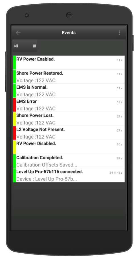
Event Log
The oneView Event screen allows you to view all the events on your system. The latest events always are shown at the top of the list. To filter by severity type tap on the All, Log, Attention, Trouble and Critical buttons.
To get more information on the even tap on the desired event to see all the details. To delete a specific event tap on the event and swipe from right to left and then press the delete button when it appears on the screen.
Note
oneView supports a maximum of 50 events. Once the event system reaches its maximum the oldest event will be removed to make room for the latest event.